Methods of generating gas flow for mechanical ventilation

The mechanical ventilator may generate flow by using the pressure gradient between the supply piped gas and the atmosphere. Alternatively, the ventilator may generate flow by means of a gas compressor turbine. These methods have the advantage of being able to generate the sort of high flows which are required for non-invasive ventilation (to compensate for leak around the edges of the mask). For most ICU ventilators, the maximum flow rate is approximately 200-250L/min. Single-circuit piston systems and double circuit bellows systems are other methods of generating flow, which sacrifice high flow rate in favour of precise gas mixture concentration and a greater degree of control over the minute volume. For these machines (eg. anaesthetic machines) the maximum flow rates may be in the order of 100-150L/min, and they are not designed for NIV, as they cannot compensate for the inevitable leak.
Neither the college SAQs for the written papers of Part 1 or Part 2, nor any of the generously worded syllabus documents, not even the workplace competency assessment (“Ventilation”) have ever mentioned this subject matter. As such, it falls into the category of apocrypha, and should be omitted from exam preparation work. It does however form an important part of understanding more generally how ventilators work, and it has therefore been included here. If nothing else, it helps explain some of the differences in the technical specifications between anaesthesia and ICU ventilators.
In summary:
There are several methods of generating inspiratory flow:
Pneumatic – By regulation of supply gas pressure (eg. piped gas from the wall, or cylinder gas pressure) – where valves are used to coordinate flow from an external reservoir.
Flow rates up to 200 L/min can be generated
This design uses the least battery power
It depends on a stable supply of pressurised gas, with a minimum 120-150 L/min flow rate and a minimum pressure of around 200 kPa.
Turbine – where a compressor is used to produce pressurised gas flow.
Potentially higher flow rates may be generated – up to 240 L/min
Can compensate for enormous amounts of leak
Requires less gas (i.e. does not rely on compressed air supply)
Still requires a compressed oxygen supply (capable of 120 L/min flow)
Bellows – where a flexible gas reservoir is compressed to produce inspiratory flow, either by a second gas circuit, or by a motorised lever, or gravity, etc.
Capable of precisely controlling the composition of the gas mixture
Suitable for low-flow gas supplies (i.e. does not require 200 kPa supply)
More complex, more moving parts and points of failure
Unable to compensate for large leak, and therefore unsuitable for NIV
Piston – a rigid chamber the volume of which is mechanically manipulated to generate inspiratory flow
Much better control of volume
Increased gas economy and quieter operation
Unable to compensate for leak
It was surpirisngly difficult to scrape together any peer-reviewed resources for this subject. As far as official references go, none can surpass the detail of James Eisencraft’s extensive chapter (Ch. 2, p.25) from Anaesthesia equipment – principles and applications (Ehrenwerth et al, 2013). This, unfortunately, would require one to purchase the whole book from Elsevier (for AU$ 219.60 at the time of writing). Moreover, the finely granular minutiae of anaesthetic machine constructuion are not expected from the CICM trainees at any level. A more accessible (freegan) resource is the excellent article by Patil et al (2013).
Requirements for flow in mechanical ventilation
The very basics of this requirement would have to be:
Enough that the patient feels that their “air hunger” is satisfied, and
Enough on top of that to compensate for leak in the circuit.
So, what would the patient need? It might be a remarkably large amount of flow. The peak inspiratory flow in a calmly breathing person seems to be 5-10 L/min, but with a bit of exercise (or respiratory distress) it can go up to 30-40L/min, according to a study by Anderson et al (2006). At peak exercise, the authors recorded peak inspiratory flow rates of around 250L/min from their healthy volunteers.
One might say that 250L/min is probably excessive. It might represent the peak inspiratory flow rate of a totally healthy adult exercising on a treadmill. In comparison, what might a typical critically ill adult require? Amato et al (1992) looked at eight ventilated patients (half had ARDS) and found that some ended up with peak inspiratory flow rates of up to 155 L/min. In the absence of better data, one might have to take that as a reasonable maximum. Let’s then add a 25% leak as the acceptable maximum ceiling (a hole in the circuit, a deflated cuff, an ill-fitted mask, a huge bronchopleural fistula). In this case, an adult ventilator would probably need to produce at least around 200 L/min of flow. This is indeed the case for most of the existing models.
Pneumatic ventilators
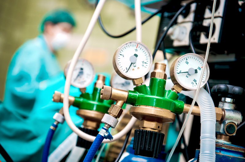
This category includes the vast majority of ventilators used in hospitals. The system depends on the supply of fresh gas from some central storage or from compressed gas cylinders, which is something abundantly available in hospitals.
That supply gas is under fairly impressive pressure, approximately 400-415 kPa. Converting that to familiar numbers, this equates to 3,040 mmHg or 4,132 cmH2O. Given that you’ll be ventilating the patient with pressures ranging from 0 to 40-50 cmH2O, a mechanism to reduce pressure is required. These usually take the form of solenoid valves which release pressurised supply gas through a small carefully controlled opening into a gas mixing chamber. Flow is generated because of the pressure differential between the supply gas line and the respiratory circuit, which is close enough to ambient atmospheric pressure.

With such high supply gas pressure, these ventilators can usually achieve very high flow rates. To use the Maquet Servo-I as an example, flow rates of 3.3 L/sec (198 L/min) are quoted in the service manual as the maximum achievable flow rate.
Obviously the ability to produce these high flow rates is dependent on the reliability of the hospitals’ gas supply. If the central supply is inadequate, the ventilator will not be able to produce such high flows. The technical specifications for these devices usually quote a minimum supply gas flow rate as 120 L/min, or a minimum supply pressure of 200 kPa (to again borrow figures from the Servo-I ventilator service manual). If the ventilator detects a lower flow rate, a “Gas Supply Failure” alarm will usually be issued.
Turbine ventilators
Ventilators which do not rely on supply gas pressure generate flow by means of a turbine which is typically referred to as a “blower”. A good example is the Hamilton-C2 ventilator, the service manual for which is available online for free. Blowers may be turbine-like (i.e. the flow is along the axis of rotation) or they can be centrifugal, as in the illustration below. Another (heavier, more energy-hungry) option is a gas compressor, which is basically s smaller scaled-down version of the large industrial-grade compressors which are used to supply compressed air into the central pipe network of a hospital. Of these designs, the blowers are the weaker- they are capable of generating relatively modest pressures which max out at 2 psi, which is still about 140 cmH2O and therefore good enough for government work.

Room air is sucked into the back of this ventilator through a filter by the negative pressure which is generated by the turbine. Upstream from the turbine, fresh oxygen gas is contributed to the circuit. The turbine then compresses this gas mixture and generates a flow which may be as high as 240 L/min according to the company propaganda document.
However, even though this compressor can produce rapid flow rates, one is not completely without reliance on compressed supplies. Unless one intends to ventilate with room air only, some oxygen needs to be trickled into the machine. Most such ventilators can accept “low flow” oxygen at 15L/min, but to give 100% FiO2 one would need to supply these ventilators with at least 120 L/min. A compressed air supply is not required, but oxygen is still needed.
Bellows ventilators
This design comes in single or double-circuit variants, but the most common is a double circuit. The “bellows” is a flexible accordion-like reservoir which stores the gas mixture which you intent do insufflate your patient with. By applying external pressure to this reservoir, inspiratory flow is generated. There are numerous ways of applying this external pressure (by a lever, a motor, a weight using gravity, etc etc) but by far the most popular appears to be the pressure of a second gas circuit.

This design has substantial merit. The most important advantage is the loss of reliance on the respiratory gas mixer to supply the driving pressure for inspiratory flow. Thus, one can afford a much greater control over the gas mixture. For instance, anaesthetic gases (present in miniscule concentrations, 1-2% of the gas mixture) are supplied with a very slow flow, which could never be suitable for pneumatic ventilation.
On the other hand, the inspiratory flow is generated by pressure from the second circuit, and so this design is still reliant on some pressurised gas source. This can be pneumatic (eg. piped gas supply) or via the use of a compressor turbine. This makes the design more complex and introduces more points of possible failure. Additionally, these ventilators cannot have a “ZEEP” mode. Zero PEEP is impossible because at all times there should be some positive pressure in the circuit – it is required to inflate the bellows between breaths.
One other problem with the bellows system is the possibility that the bellows might be damaged. Any hole in the bag will then allow the driving gas to mix with the inspiratory gas, which completely destroys the precision of your carefully arranged gas mixture composition. Furthermore, the pressure of the driving gas may be well in excess of what would be required to ventilate the patient, and if this highly pressurised gas has unregulated access to the patient’s respiratory tract, barotrauma may result.
Piston ventilators
These are a popular alternative to the bellows system. Instead of the circuit gas inflating an accordion-like bag, in the piston design a plunger pulls and pushes the fresh gas mixture inside a rigid cylinder.

This design has some merits:
Control over the tidal volume is more precise than with any other model
There is no reliance on any pneumatic power, and therefore the use of gas is more economical (i.e. gas is not wasted on doing the sort of mechanical work that could be more effectively outsourced to an electric motor)
There is no PEEP requirement in the circuit – ZEEP is possible
These are probably the quietest ventilator design.
There are of course some disadvantages. For example, if there is a significant leak, this ventilator will not be able to compensate for it, and the delivered tidal volume will be significantly diminished. Like the bellows, it’s certainly not a design which one might use for NIV.


